Corbin Hydro-Presstm
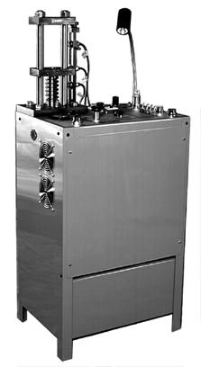
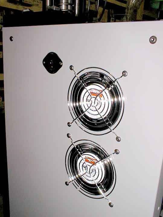
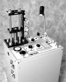
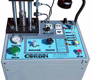 The world's most powerful (and popular) hydraulic power swaging and reloading press, Corbin's Model CHP-1, has been again revised and improved, with even more reliable electronic position transducers, redesigned powder-coated steel cabinet with integral hydraulic tank and forced air cooling, and new features to interface with Corbin's automatic strip feeder/decoiler and other accessories.
The CHP-1 has been produced for more than 40 years, starting with the original Mark I. The prior version, Mark V, is used by nearly every custom bullet making firm in the world today, outselling every other type and brand of bullet making press for commercial custom bullet manufacturing, military prototype work, research and development labs and short run test production at defense industries. Today's Mark VI retains all the reliability and features that have made Corbin's Hydro-Press the world's leading design, with even greater freedom from maintenance and more functionality, with a taller cabinet design.
The CHP-1, Mark VI, weighs 350 pounds (shipping weight 405 lbs), has a 22 inch by 15 inch floor space, and runs on either 115-120 volt 50 or 60 Hz standard household current (USA), or 240 volt 50 or 60 Hz standard overseas power (with optional A-220v kit).
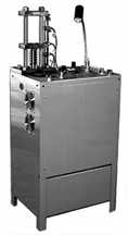
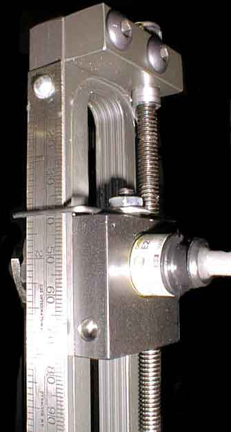
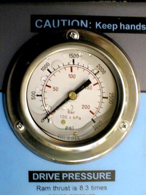
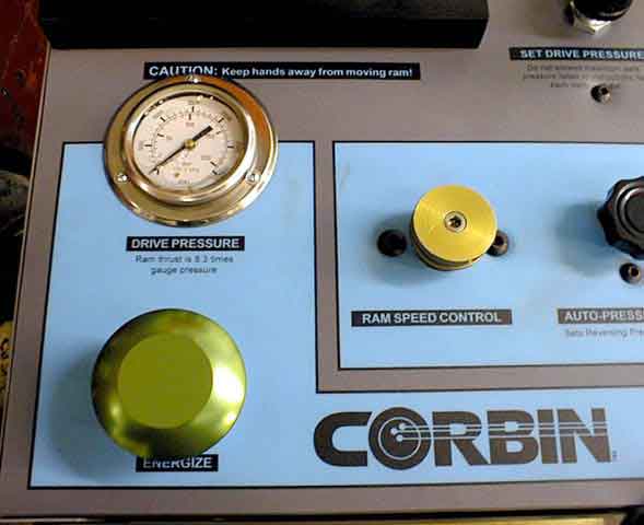
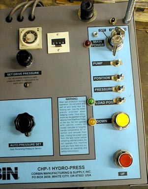
The Mark VI is built with a taller cabinet, adding four additional inches to the height of the previous models. The additional cabinet height places the control panel at a more convenient position for the operator and makes it easier to observe the operation of the die and external punch during insertion of components. The pressure gauge is now equipped with an internal damper or "dash-pot" style of stabilizer, rather than the former glycerine-filled version. This makes the gauge easier to read and eliminates the air bubble which was visible through the glass (previously required for thermal expansion of the glycerine). The gauge face and needle are now the same appearance as a "dry" gauge, but with the benefit of vibration damping to extend the life of the gauge and eliminate needle vibration, compared to lower-cost gauges without this feature.
The motor is now a heavy duty Baldor rather than the former Leeson brand used in Mark V versions. The new motor has a heavier frame and a cast wiring junction box instead of the sheet metal, and does not have the (unused) horizontal mounting legs on the side. These differences will help identify the version of used CHP-1 presses over the coming decades, although the height difference in the cabinet is the most visible change.
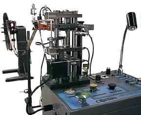
With 6-inch stroke length, and enough power to swage 1-inch diameter cannon shells, the Hydro-Press is a true multi-purpose machine. Some of the things it can do, with the proper set of dies, include:
- Bullet Swaging from .123 to 1.000 inch diameters, up to 3 inch long projectile.
- Making bullet jackets from copper, aluminum, steel or brass tubing.
- Re-manufacturing fired or pulled bullets to nearly new specifications.
- Forming powdered metal tungsten and other exotic bullet constructions.
- Drawing bullet jackets from flat strip, including long heavy jackets like the 50BMG.
- Extruding lead wire, hollow lead tube, or lead came for stained glass work.
- Making detonators, grenade primers, and other formed round tubular devices.
- Reloading ammunition of any size with conventional or special reloading dies.
- Swaging finned shotgun slugs with helical twist and hollow cavities.
- Manufacturing fishing tackle, spinners, spoons, and bass lures from copper or brass.
- Punching, forming, drawing, and other precision metal fabrication operations.
- Foming pressure-linked plastic materials into sabots, tips, and other round shapes.
- Swaging perfect round balls for muzzle loaders in any diameter.
The CHP-1 is the machine of choice for any custom bullet business, because it can do everything from making the lead wire to drawing the jackets, swaging the bullets, and even reloading ammunition with the bullets it just made. While it is a hand-fed press (with the one exception of automatic copper strip feeding with the CSU-1 strip uncoiler and JMK-2 automatic jacket drawing head), it is a perfect match for custom bullet business volume, bullet pricing, and limited capital investment. Often, a company will choose to grow by adding more Hydro-Presses rather than spending six figures on the next step up, automated transfer presses, since the Hydro-Presses can make any caliber within a few seconds of setup time, whereas the high speed automatics not only cost as much as twenty Hydro-Presses, but are dedicated solely to one product at a time and are very slow and expensive to change to another.
|
How It Works
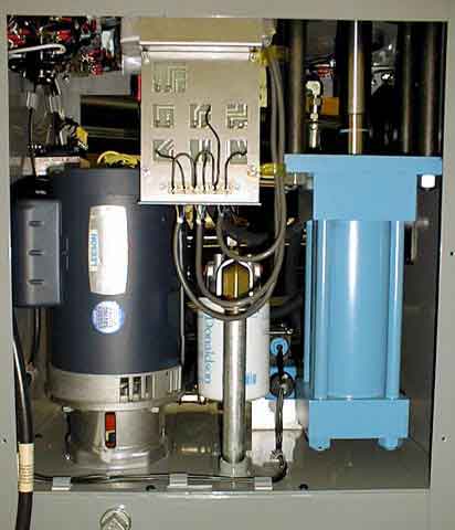
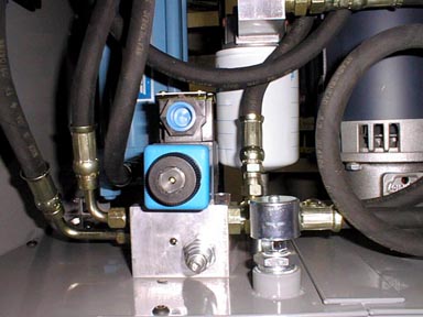
The Corbin Hydro-Press is powered by a 1.5 HP electric motor within the cabinet, vertically mounted. The shaft of the motor fits through a mounting, which in turn joins the shaft of a two-stage hydraulic pump inside the lower third of the cabinet. The lower third of the steel cabinet is a closed hydraulic reservoir holding about 8.5 gallons of non-foaming Chevron AW-40 hydraulic fluid. It is designed with a baffle and a top-mounted filler/breather just inside the front cabinet.
HYDRAULIC DIAGRAM
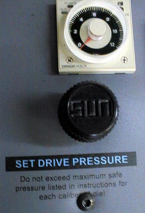
The oil is pumped to a three way solenoid valve, which controls the direction of oil flow. In the idle or normal position, the valve dumps oil quietly back into the tank through a sub-micron oil filter (spin-off type, similar to but much finer than your car oil filter). When you press the ENERGIZE and UP buttons on the top pannel, the solenoid valve switches to allow oil to flow into the bottom of a 3.25-inch bore by 6 inch long industrial drive cylinder. The oil pressure is regulated by an internal safety valve, and a top panel drive pressure set knob that runs a temperature-compensated pressure regulator valve. You can set the drive pressure anywhere from a minimal 100 psi to as much as 2000 psi. Drive pressure is translated into 8.3 times as much ram thrust by the cylinder, and internal die pressure is determined by dividing this thrust by the area of the swage die cross section. More than 120,000 psi can be generated in some dies, although a far lower limit is imposed by the breaking strength of a die in most cases.
A book (Power Swaging) which comes with the press contains a table of safe die pressures for a given cross section (usually the caliber, but not always...a core swage die can have a much smaller bore than the caliber it is intended to fill). A high grade pressure gauge on the top panel monitors drive pressure at all times.
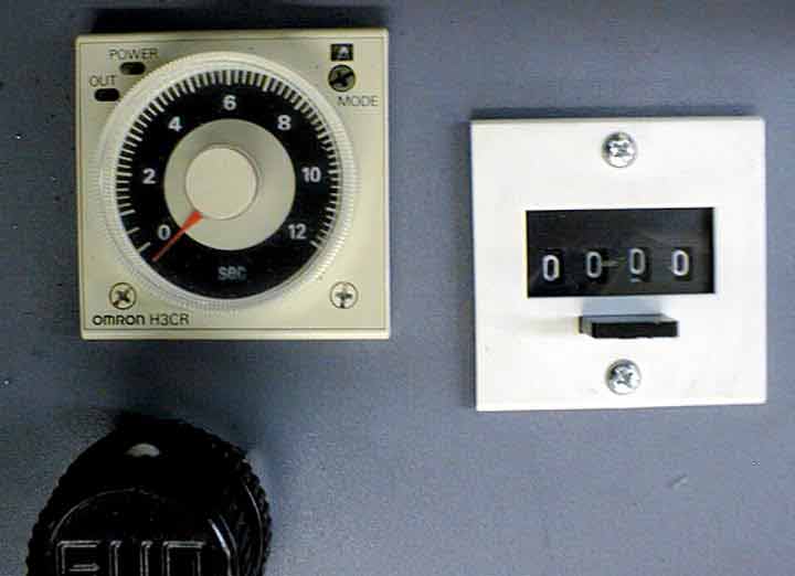
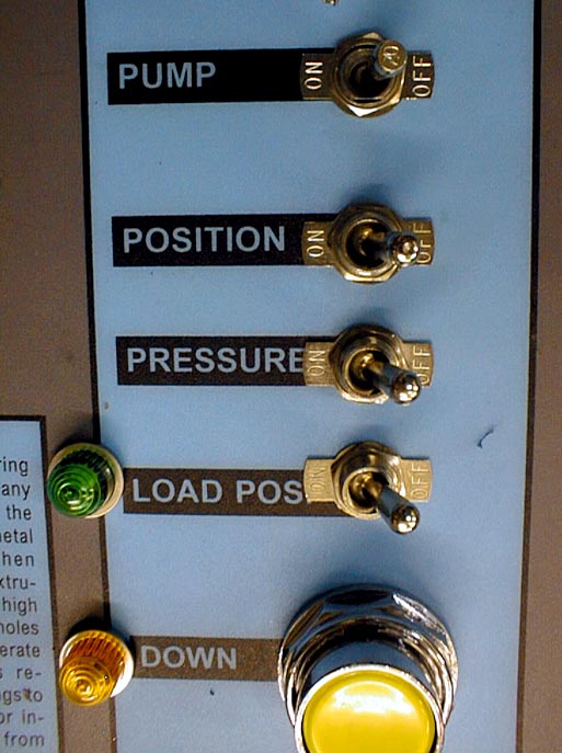
Electronic dwell timing can be set to precisely control the length of time that pressure is applied, down to the millisecond. The Mark VI includes dwell time controls for both the top and bottom of the stroke, so a delay can be introduced during ejection to allow sufficient time to break "air-locks" and eliminate the impact of a sudden reversal. The press can also be set, by means of simple toggle switches, to operate according to certain prewired cycle programs. With the pressure reverse switch turned off, and the position switch turned on, the ram travels up until it is detected by the top position transducer, which is on a standard to which three adjustable transducers are mounted. When the transducer detects the presence of the ram at your definable top setting, it stops the ram travel by moving the solenoid valve to the center position, holding pressure at the top of the stroke.
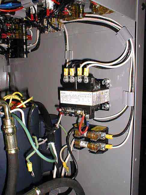
WIRING DIAGRAM
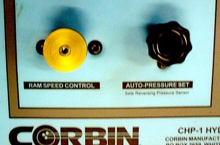
If the pressure switch is turned on, it passes over-riding control to a sensitive pressure transducer, which can be easily adjusted with a hand knob. This transducer monitors drive pressure, and causes the ram to stop when a pre-set pressure is reached. Thus, you can set the press to stop on reaching a certain position, or a certain pressure. One setting backs up the other to prevent accidents. Next to the pressure reverse control is a speed control so the ram can travel at any rate, from zero to barely creeping along, to 2 inches per second.
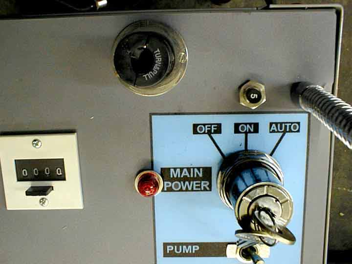
Because the press uses a two-stage pump with feedback control, the power consumption is very low while the ram is moving up and down. The only time there is any significant power use is when a bullet is actually being subjected to pressure, at which point the pump switches from high speed low pressure mode into a short burst of high pressure at low speed. The amount of energy used is a fraction of that required by a single stage pump without feedback, making it practical to run the Hydro-Press in any garage, den, or even trailer house, provided the wiring is at least 12 gauge copper with a 20 ampere breaker. The press itself contains a 20 ampere circuit breaker switch as the main power control, as well as a 5 ampere push-button breaker for the logic and control circuits.
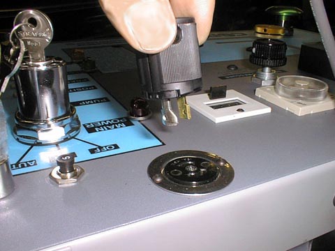
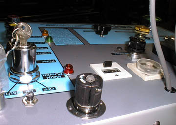
The CHP-1 Mark VI has a three position key switch that controls the power and functions. In the off position, only the fans and inspection lamp are functional. In the on position, the press can be run in manual mode only, stopping as soon as a hand is lifted from either the Energize or the UP button, except on the down stroke. In the Auto position, a red warning light comes on, and the press can be started in an automatic up and down cycle, with or without pressure reverse. It can also be operated in a one-shot automatic mode, where a person drops in the part, presses the Energize and UP buttons in the proper sequence, and then lets the press handle the stroke cycle while the operator does something else. The ram will then stop at the LOAD position, set by the center position transducer, on each stroke, and wait to be loaded again.
For safety, the key can be removed with the press in the manual or off position, preventing automatic stroke operation.
On presses made prior to August 1, 2011, at the rear of the press, a shunt plug fits into a socket that is intended as a sensor inlet so that the optional strip feeder can shut off the press, in automatic operation, when the 50 or 100 pound coil of strip runs out. This features was almost never used, so it has been discontinued.
On presses made on or after August 1, 2011, the shunt plug is not used, and the socket at the rear of the press top is connected so that it receives 115v from the logic and control circuits, limited to 5 amps, whenever the press is in the "down" stroke mode. The earlier shunt plug should not be used on these presses, as it will cause the 5 amp logic circuit breaker to open. Instead, the socket is used for an optional automatic jacket stripper, which can be purchased separately and mounted on the press head. The jacket stripper can be operated manually, or it can be shifted in and out of position to strip drawn jackets from their drawing punch, using the soleniod-operated power shifter. The power for the devices comes from this socket. When the press ram begins to go down, the solenoid shifts a stripper plate to catch the mouth of the jacket being drawn, and the punch continues down. This pulls the jacket from the punch automatically. When the ram reaches the bottom of the stroke, the power is removed from the solenoid and a spring returns the stripper plate to the "rest" position, ready for another jacket.
Presses made after 2019 (Mark VI) have a taller cabinet than previous models.
For full details and pricing on the Hydro-Press and the -H dies which fit it, see the Corbin Price list and read the book "Power Swaging". This book also comes with the press as an operating guide. The content is also available free to download on www.Swage.com document server.
SHIPPING INFORMATION


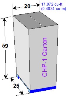
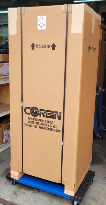
The CHP-1 is shipped in heavy duty carton on skids: 20-in deep, 25-in wide, 59-in tall.
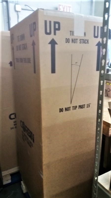
Aprox. 405 lbs shipping weight. The carton is shipped by truck, and has a tip indicator secured to the side. The carton MUST remain upright within 15 degrees of vertical at all times. Use a lift gate or fork lift to load and offload. The press arrives ready to plug in and operate, except for export models using adjustable 240v power, which will require proper power mains connector for local standard. Domestic models using 115-125v 60hz come with standard 3-prong plug for standard US electrical code outlet (for ordinary household wall socket, 115v grounded 3-wire connection).
IMPORTANT:
When you receive a Truck Shipment such as the CHP-1 Hydro Press, do not sign anything until you have carefully inspected the package for any sign of damage or tipping. Check the TIP-N-TELL indicator on the side of the carton. Read the instructions on it. If it indicates the package has been tipped, refuse delivery or at the very least sign that the package was received in damaged condition. If you do not receive a carton on a custom pallet that looks similar to the photos above, and you ordered a Hydro Press, refuse the shipment.
The CHP-1 will always be shipped in a carton custom built to protect it. It will never come wrapped in plastic only, or without the heavy carton and padded internal corners and the sturdy custom skid to which the carton is secured. If it does, the package was mishandled, the carton removed or destroyed in transit, and there is likely damage to the product. Do NOT accept the shipment if this is the case! Do not worry about making the truck driver cry. He will get paid regardless.
If you sign the receipt without noting damage, you are signing that the package was delivered in acceptable condition, and you are releasing the truck line of liability. This is true even if there is mishandling damage that you may not yet have noticed until you unpack the carton. In fact, if there is so much as a fingerprint on the carton, any tears or dents, and certainly any sign of oil spill or hydraulic fluid leakage, either refuse the delivery due to damage or sign that you received the shipment in damaged condition.
You don't have to do anything if there is no actual damage to the content, of course. But you cannot always tell if the package was turned over, fell off the loading gate, or was otherwise subjected to severe shock and trauma during handling, It is always safer to retain your insurance rights by noting potential damage than to take a chance. The "received in damaged condition" note is insurance just in case. It doesn't necessarily mean there is actual damage to the content, but only that you suspect it is possible.
Once you sign without any such notation of damage, you own it whether or not it was turned to scrap metal inside the carton, and the insurance company will gladly point out that you signed the default terms "received in acceptable condition" releasing liability for the trucking firm. Any shipping damage is then your problem, not the insurance firm covering the trucking company. Or between your lawyer and the team of legal experts on the insurance company staff, retained by the trucking firm to protect them from claims that have been negated by the consignee signature.

|
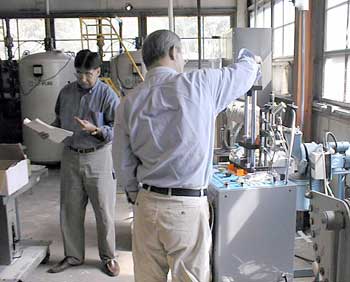
Not far from Parsippiny, New Jersey, is the Picatinny Arsenal, home to US Army advanced weapons research and development. Building 1609, a tin-roofed 1920's style barracks-like structure, houses an extensive laboratory which includes two Corbin Hydro-Presses which were used by Ph.D's during the development of the service-wide Green Bullet project. Corbin delivered and set up the presses in 2001 and 2002 for this work.
|
|
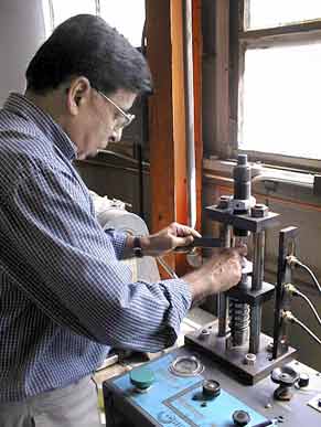
One of two Ph.D's working on compounds for the Green Bullet project, Dr. Kapur uses a Corbin HydroPress to form lead-free bullets from powder metal mixtures in this 2001 photograph. Corbin's presses and dies have since been used by dozens of agencies and defense contractors to further the development of advanced projectiles, including special remote control models for assembly and disassembly of 40mm ammunition (the limit of the standard CHP-1 is 25mm).
|

|
The exterior of building 1609 would scarcely warrant a second look, but this is a small portion of the array of sophistocated lab equipment inside! The ARDEC related development work done in this building would seem more likely to be housed in a gleaming glass and steel structure, not one where the sparrows sometimes enter through gaps in the ancient wood-framed windows.
|
|
Corbin Hydro-Presses at the Picatinny Arsenal, during the early days of the Green Bullet project. The CHP-1 press and Corbin dies are also in use at Frankfort Arsenal, Oak Ridge, China Lake Naval facility, Eglin AFB weapons labs, and other research and development facilities.
|

|
Across the street from the lab, this indoor firing range is large enough to drive a tank into one end, and fire artillery shells into the backstop at the other end!
|
|
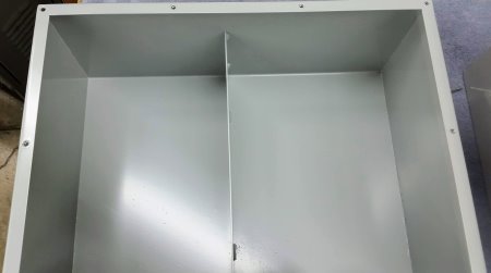
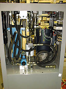
CHP-1 Hydraulic Tank Details
Here are pictures of the hydraulic tank inside, with the top removed, so you can see the total inside and outside powder coated finish that protects every component of the cabinet. The baffle across the tank reduces turbulence and allows bubbles to escape before the fluid is picked up by the pump.
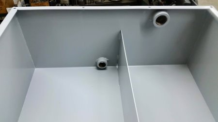
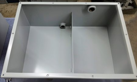

The two threaded ports shown are the drain port (bottom) and the combined fluid level check and access port for the two-stage pump unloader valve. This valve, also called the "switch-over" setting control, is a spring loaded valve that determines the pressure at which the pump changes from high volume/high speed to the low speed/high pressure operation.
This is normally set at about 450 psi but is adjusted for best performance with the current component parameters. The valve is screw-driver adjusted to control the point at which both the high displacement stage and the high pressure/low displacement stage operate together, or switch to just the high pressure side. The ram will move at about 2 inches per second until the resistance against it reaches the point where the hydraulic pressure trips this switch-over or unloader valve to shut off the high volume stage. Then the pressure rises and the ram speed slows, so that the total horsepower can remain the same, reducing the power requirements for the press.
Since the switch-over point only happens when a load is on the press (that is, it has moved the die/punch into contact with the material being formed and has come to the stage where pressure is more important than speed), the speed change normally goes unnoticed. The main purpose for the high volume/high speed movement is just to get the tools (die and punch) into position, pushing the material into the die or taking up "slack" so to speak.
When the material is contacted, it offers resistance, which raises the system pressure (but no higher than the maximum set point, adjustable from the PRESSURE SET control, or if the pressure reversing switch is ON, no higher than the point at which the PRESSURE REVERSE control is set.)
The increased system pressure balances the spring force set on the switch over valve, closing the valve, and closing the path between high pressure and low pressure stages of the pump. This lets the high pressure side of the pump handle the "end of the stroke", up to the pressure limiter setting. The pressure limiter is not inside the tank. It is a cartridge valve on the base of the solenoid manifold, inside the press, mounted on top of the tank.
Caution:
Tempting as it may be to some, it is not a good idea to adjust the pressure limiter. It is set to about 2,000 psi for a reason. If a particular material does not form properly with the maximum system pressure, it probably will break expensive dies or bend and crack punches if higher pressures are used to force the issue. The right answer is to determine why the material is not forming with normal pressure. Perhaps it is simply too hard. Perhaps not enough or the incorrect type of lubricant is being used. A "bigger hammer" seldom is the way to cure technical problems.
The pressure switch over or unloader valve also is set where it is for a good reason. Changing this setting does not give the press more power. It simply unbalances the proper load handling of the two stage pump, which may cause oscillation of the ram in auto-reverse mode, or other unexpected issues to arise. The adjustments on the top of the cabinet are designed to operate properly with the settings carefully established by those inside the cabinet. The book "Power Swaging" describes how to set the top panel controls. It does not provide the technical expertise needed for correct adjustment of the unloader or limiter valves. These are not provided for the purpose of normal operating adjustment but only for necessary factory set-up with the rest of the controls.
Access Ports
The 1-inch threaded port closer to the top rear of the tank is the access port and also serves as a fill level indicator. If you can see or feel hydraulic fluid just below the level of this port, the tank is properly filled with about 8.5 gallons of AW46 weight hydraulic fluid (or equivalent). If the fluid level is considerably below this level, it means a leak or spillage has happened at some point, and fluid should be added. Contact Corbin for the proper kind and weight of hydraulic fluid. Do NOT add such things as brake fluid or power steering fluid! These can cause serious damage to the seals of the valves, pump, and cylinder. All "hydraulic fluids" are NOT the same!
The fluid is not consumed or contaminated in normal use. Hydro-Presses have been operated for twenty years or more without adding or changing the fluid, although changing the filter every 2000 hours or so of operation is recommended. There are no combusion contaminants, as with an automobile engine, to cause deterioration of the fluid. It is a sealed system, so unless somone removes connections or components and exposes the fluid system to outside dust and contamination, or the storage conditions are such that alternate cold and heat causes water condensation within the unit, there is seldom any need to replace or add fluid. The main source of any wear contamination would be fine dust from wear of the pump vanes, which should be trapped in the filter.
To change the fluid, the drain port on the rear of the tank can be opened by removing the screw-in plug, and the fluid caught in a large drain pan. The fluid should be taken to a proper disposal station or site in accordance with local regulations. If the tank is contaminated, it should be flushed with a gallon or so of the same fluid to wash out remaining materials. The filter should be changed, and then the tank refilled (with the drain plug screwed snugly back in place, of course). The top access port, in the back, should be open to see when the fluid is just below the opening. It can be seen with a small penlight shining in the open port.
|


