| Home | Presses | Intro | Site Map | P.R. | Chemicals | Answers |

|
| Prices | Specials | How To | Bullets | B.Makers | Books | Classified | |
| Topics | Jackets | Terms | Training | Software | Products | Contact us |
| Home | Presses | Intro | Site Map | P.R. | Chemicals | Answers |

|
| Prices | Specials | How To | Bullets | B.Makers | Books | Classified | |
| Topics | Jackets | Terms | Training | Software | Products | Contact us |

| |
|
S-Press |
Hydro-Press |
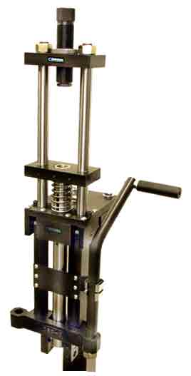
Corbin CSP-2 Mega-Mitetm
|
Operating Characteristics
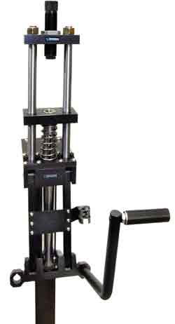
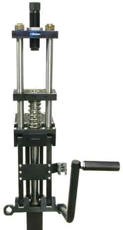
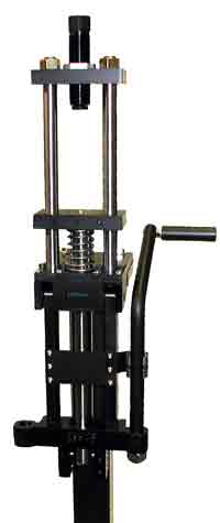
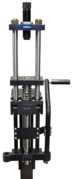
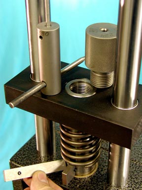 The operating handle can be used for left or right hand operation. Two handle options are available, the side-bar roller handle CSP-2SH, and the optional long high-torque handle CSP-2LH. The side-bar roller has a horizontal rotating steel grip and is about half the length of the long handle. You may specify either handle with the press, or purchase either handle as an optional add-on item. If not otherwise specified with your order, the press will ship with the CSP-2SH. This handle is adequate for reloading and most swaging operations, and requires less physical movement of the arm and body than the long handle. For maximum power, the long handle delivers about twice the leverage or mechanical advantage, but is more tiring to use for long production runs. Bullet makers may own both handles and change them depending on the kind of work to be done.
The handle moves in a full 180-degree arc for up to 20% more leverage. In short-stroke (swaging) mode, the press delivers over 220% more power than the largest cast-frame reloading presses. With a tensile strenth of over 180,000 psi, virtually any bullet that can be imagined can be swaged. Ejection of bullets is positive on the down-stroke. A set of four different heights of knock-out bars is provided, to match different lengths of internal punches. The length of the punch head controls the weight range of a given die. The total length of the punch plus the knock-out bar height is a constant: a long punch uses a short knock-out bar, and vice versa. The K.O. bar slips through a slot in the ram, under the head of the punch (and under the retraction spring that surrounds the ram: the ram is raised to release pressure and allow the K.O. bar to be inserted). When the ram is lowered, the K.O. bar comes to rest on the inch-thick steel base plate. As the ram continues downward, the punch is stopped and pushes the bulet out of the die. Dies which use an ejection pin, such as a point forming die, need to have a positive retraction system to pull the pin out of the die cavity while the bullet tip is being formed. A quarter-inch diameter hole through the head of these punches aligns with the ram slot, and a spring-steel quarter-inch diameter retraction pin slips through both, under the retraction spring. The spring compresses against the retraction pin and pushes it down, against the knock-out bar. Until the K.O. bar comes to rest on the press base plate (during the downward stroke), the ejection pin remains out of the die cavity so the closing jacket tip won't form around the pin. When the ram is lowered, the retraction pin is pushed up along with the spring, and the bullet is pushed out of the die. Most -H swage dies have the retraction pin hole in their internal punch head, even if positive retraction is not absolutely needed. It is always helpful, even if inserting the component would push the internal punch down without much effort. |
For dimensions of both the CSP-1 and CSP-2 in table form with drawings, click here.
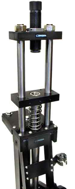
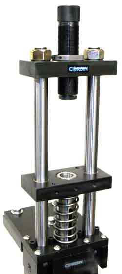
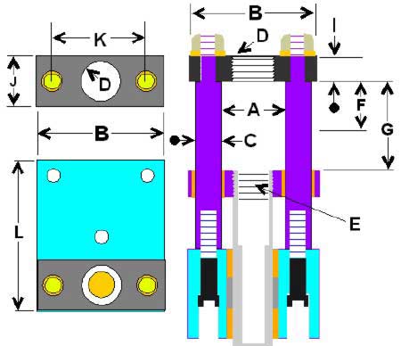 The top plate or head plate of the CSP-2 press is 6 inches wide (B on drawing), 1 inch thick (I on drawing), and 3 inches deep (J on drawing). The head is secured by two 7/8-14 threaded nuts, which have been lathe turned to square the mating surfaces with the axis (most standard bolts and nuts are not true 90-degree square). The center spacing between the two 1-inch diameter vertical rods is 4 inches (K on drawing). The 7/8-14 nuts are secured so that two flats face each other and provide 2-3/4 inches of space across the top of the press head (dimension C on photo) for the lock nut (which is also lathe turned for true 90 degree mating surfaces).
The floating punch holder at the press top adds 6 inches maximum height to the press in full up position. There is 15.5 inches from the top of the press to the bench on which it mounts. It is 15 inches from the bench top to the lowest point on the press itself, without the handle (dimension F on photo). 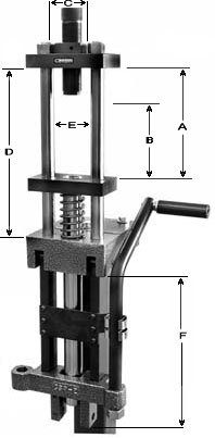 The space between the two 1-inch diameter guide rods is 3 inches (E on photo). The press has three strokes or ram travel distances, depending on the setting of the ram to toggle pin. In the long stroke (reloading) mode, the space between the lower side of the head, and the top of the ram plate, is 9.5 inches with the ram down (A in photo) and 3.5 inches with the ram up (B in photo). With the press set for the short stroke or swaging mode, dimension A is 8 inches and dimension B is 5-1/8 inches (in the photo). A middle stroke provides a stroke that is in the middle of this range. The purpose of the different stroke settings is to best adapt the working space, leverage, and position of the punch relative to the die for drawing jackets, swaging bullets, or reloading.
The distance from the top of the base or mounting plate to the bottom side of the press head is 12-1/2 inches (D in photo). The size of the mounting base itself is 6.5 inches wide by 8 inches deep (L in drawing). At least 3-1/4 inches of the 8-inch base plate projects in front of the bench, leaving a space of 4-3/4 inches for the mounting depth from the edge of the bench. Top Plate Threaded hole (D in drawing) is 1-1/2 x 12 threads per inch, which fits standard C-H and RCBS 50 BMG reloading dies. A 1-1/4 x 12 adapter is available for other dies, as an option. The press comes with a 7/8 x 14 adapter for regular reloading dies, and a 1 x 14 adapter as well as 1 x 12 adapter can be ordered for other special dies. Ram Threaded hole (E in drawing) is 1 x 12 threads per inch. The press comes with an adapter for 7/8 x 14 threaded shell holders (standard RCBS and C-H shell holder as well as Corbin shell holder), and a screw-in T-slot for standard caliber shell holders. A dimensioned drawing for a mounting plate that accepts either the CSP-2 or the smaller CSP-1 press, and can be used as a template for making holes on a loading bench, is available by clicking here. |
Options for the press include arbor press anvils (which convert the punch holder and the ram for benchrest-type non-threaded reloading dies), a quick change floating punch holder, jacket and bullet reducing dies, bullet swaging dies, jacket making dies for copper tubing or for flat strip, press rod extensions, a kit for using -S dies, and a self-supporting floor stand. Corbin also provides quality 50 BMG reloading dies at an attractive price.
|
|
Order from:
|
|
| Home Page | Price List | E-Mail Sales | Site Map | New Products | Auto Q&A | Terminology |
| Retirement | Specials | Real Estate | Software | How to swage | Classified Ads | Feedback |